
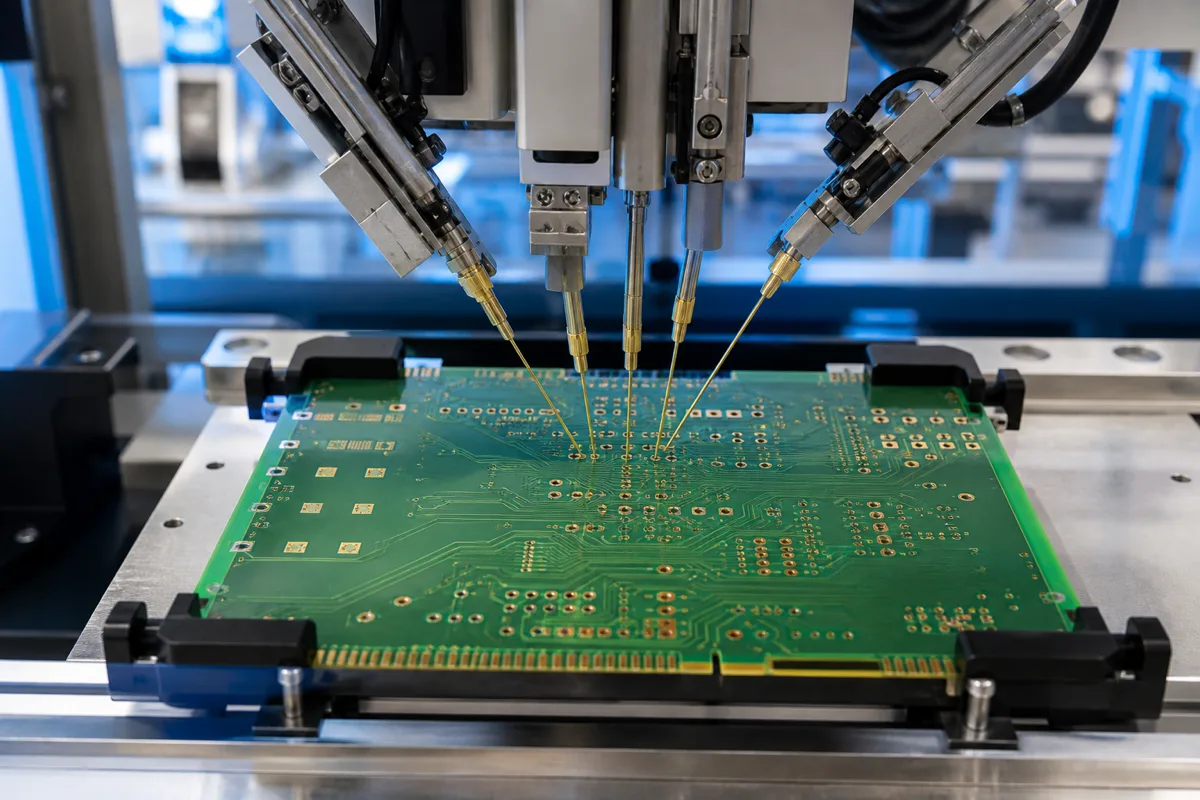
A 100% PCB electrical test verifies that the tested bare-board connections match the supplied netlist, but it does not prove every physical, assembly, or in-service reliability requirement. For OEM and EMS buyers, the useful question is not simply whether a board is “100% e-tested.” It is what data, method, limits, and coverage define that test.
This distinction matters most on multilayer boards, dense interconnects, via-critical designs, and repeat-production programs. A clear test specification helps the PCB manufacturer select the right method, identify critical nets, and avoid a false sense of security at final inspection.
What 100% Electrical Testing Usually Means
For an unpopulated PCB, electrical testing normally compares the finished board with an approved electrical reference, usually a netlist derived from the design data. The test checks whether required conductive paths are continuous and whether separate networks remain electrically isolated.
In practical terms, it is intended to detect problems such as open circuits, unintended shorts, and incorrect network connectivity within the programmed test conditions. The exact resistance and isolation limits, however, depend on the test specification and equipment settings.
IPC-9252B frames electrical testing around verifying the integrity of conductive networks on unpopulated printed boards. It also makes an important limitation clear: electrical test alone does not establish assemblability or every physical requirement of the finished board.
What the Test Verifies and What It Does Not Prove
| Electrical testing can verify | Electrical testing alone does not prove |
|---|---|
| Continuity of programmed nets | Final assembly workmanship |
| Isolation between networks | Component placement or solder-joint quality |
| Opens and shorts under defined limits | Mechanical dimensions and surface appearance |
| Connectivity against the approved test data | Long-term performance under thermal or mechanical stress |
| Some resistance-related anomalies when suitable limits are used | Every latent via, plating, material, or impedance risk |
A board can therefore pass electrical testing and still require other controls. Automated optical inspection, X-ray, microsection analysis, impedance testing, solderability checks, ionic contamination testing, and assembly inspection answer different questions. The appropriate combination should follow the design and application risk.
Flying Probe Testing Versus Fixture Testing
Flying probe testers use programmable moving probes to contact test points without a dedicated bed-of-nails fixture. This makes them flexible for prototypes, engineering changes, and lower-volume production because test data can be updated without building a new fixture.
Fixture testing uses a dedicated contact fixture to reach many test points rapidly. Its higher setup effort can make sense for stable, higher-volume programs where throughput is important. Neither method is automatically “better” for every order. Board complexity, accessible test points, volume, revision stability, limits, and reporting requirements should drive the choice.
For a broader comparison of inspection technologies, see our guide to AOI, X-ray, and flying probe testing.
Why Critical Vias and Dense Designs Need More Attention
Standard continuity results do not always describe the full condition of a via or plated connection. A marginal feature may conduct under the test conditions yet remain vulnerable to thermal cycling, mechanical stress, or later assembly processes. This does not make electrical testing ineffective; it means the test should be part of a risk-based quality plan.
For designs that rely heavily on blind or buried vias, via-in-pad structures, small annular rings, heavy copper transitions, controlled impedance, or high-current paths, buyers should identify the critical features before production. The manufacturer can then review whether tighter electrical limits, four-wire resistance measurement, impedance coupons, microsections, thermal stress evaluation, or other targeted controls are appropriate.
Six Questions Buyers Should Confirm Before Production
- What is the electrical reference? Confirm whether the test program is generated from the supplied IPC-356 netlist, Gerber-derived data, or another approved source.
- Which method will be used? Ask whether the order will use flying probe, fixture testing, or a combination, and why it fits the quantity and design.
- What are the continuity and isolation limits? “Pass” only has meaning when the relevant thresholds and exceptions are understood.
- Are all required points accessible? Limited access, special finishes, or design constraints may affect the achievable test coverage.
- Which nets or features are critical? Identify power paths, safety-related circuits, fine-pitch interconnects, via chains, or other high-risk features that need special attention.
- What records are available? Agree on the test report, traceability, exception handling, and retention requirements before release.
Use Electrical Testing as Part of a Complete Quality Plan
The strongest specification connects design risk with the right manufacturing and verification controls. Electrical testing is essential for confirming bare-board connectivity, but reliable production also depends on material control, drilling and plating discipline, dimensional inspection, process monitoring, and clear engineering communication.
Cheerise Circuits supports prototype and production PCB projects with DFM review, electrical testing, inspection planning, and documented quality controls. Review our PCB quality and manufacturing capabilities, or contact our engineering team to discuss the appropriate test coverage for your board.
Frequently Asked Questions
What does 100% electrical testing mean for a PCB?
It generally means every programmed bare-board network is checked for continuity and isolation against an approved electrical reference. The meaning still depends on the test data, accessible points, limits, and agreed exceptions.
Can electrical testing detect every via defect?
No. It can identify opens, shorts, and some resistance anomalies under defined test conditions, but it does not by itself prove the physical integrity or long-term reliability of every via. High-risk via structures may need microsection, resistance, thermal, or other targeted verification.
Is flying probe testing suitable for prototypes?
Yes. Flying probe testing is commonly suited to prototypes and lower-volume orders because it does not require a dedicated test fixture and can be reprogrammed when the design changes. The final choice still depends on complexity, access, test limits, and schedule.
What should buyers specify before PCB production?
Provide an approved netlist, identify critical nets and structures, define any special continuity or isolation requirements, confirm the test method and reporting needs, and state any additional reliability or inspection requirements before manufacturing release.